Support Portal
As a regular operator without administrator rights, you have access to the Support Portal. This portal is designed for efficient searching of CPE devices, monitoring their status, and managing settings or basic configuration parameters.
Table "Devices table"
This is the main table in the Support Portal. It contains all devices that have ever interacted with DMS. Each device in the table is characterized by parameters such as Status, Actions, CPEID, Vendor, Model, and others.
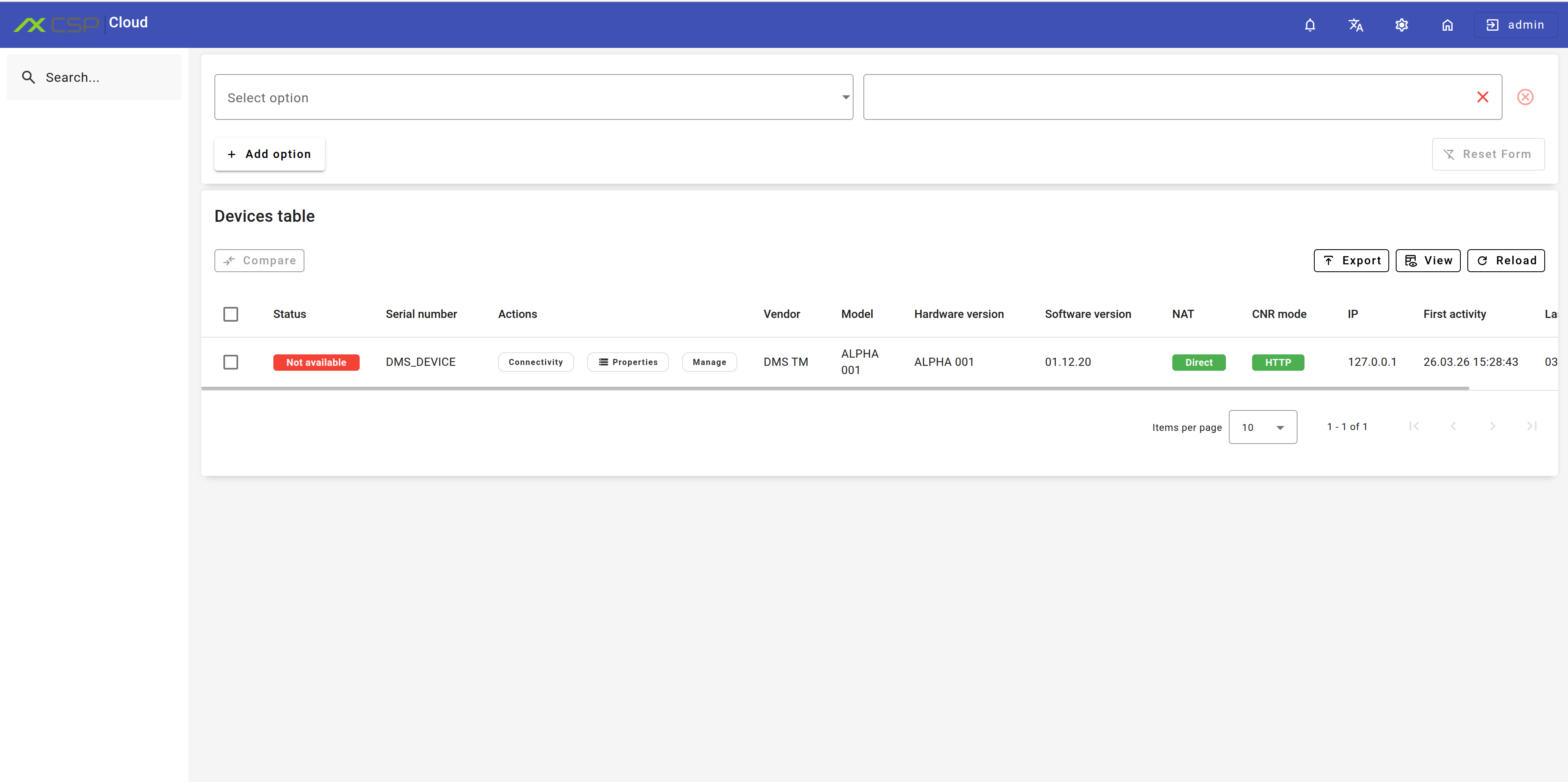
The "Status" field shows the device's state relative to DMS. It does not display the device's status within your network.
Description of "Status" field values
| Status | Description |
|---|---|
 | CPE is online and available for ACS |
 | Connection request to CPE is being sent |
 | Connection request has been sent, awaiting response from CPE |
 | New CPE registered in the database |
 | CPE is unavailable: no active session or connection request remained unanswered |
 | An error occurred during ACS interaction with CPE |
 | CPE firmware upgrade has been initiated and is in progress |
 | CPE reboot has been initiated and is in progress |
 | Request failed authentication |
The "NAT" field shows whether NAT was detected between the device and DMS.
"Actions" Buttons
For each record in the table, three action buttons are available, providing various device management capabilities:
- "Connectivity" — clicking this button initiates the "Connection Request" mechanism, described in detail in section 3.2.2 of the TR-069 specification. The result of this mechanism is displayed as an informational message at the bottom of the page, and may also change the device's status in the table.

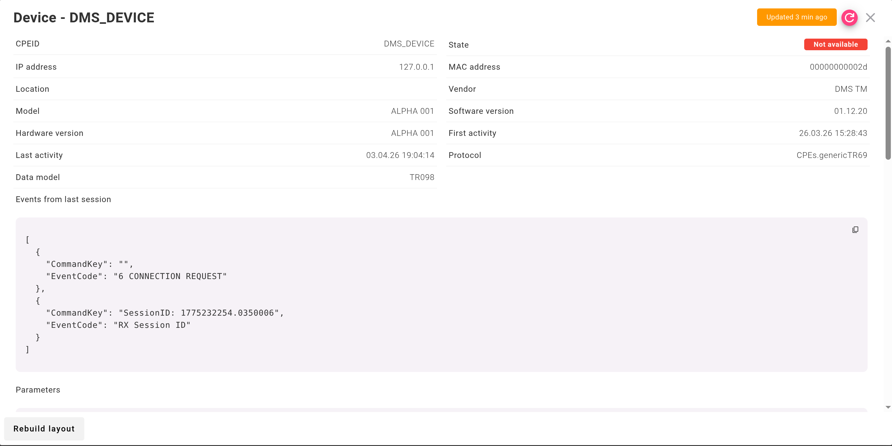
- "Properties" — this button opens a dialog box containing complete information about the device record in the "Device table". Here you can review all device details in a convenient format.
- "Manage" — the most important action button, which opens the device card. The card is automatically formed based on parameters available on your device and provides advanced management capabilities.
Search
Search in the table works according to the description in this section.
Available search parameters and their description
| Parameter | Value |
|---|---|
| "Status" | Displays for each device whether it is in working condition ("Online") or not ("Offline") |
| "Serial number" | Numerical identification number assigned to CPE |
| "Vendor" | Company manufacturing the CPE |
| "Model" | Alphanumeric index designating a set of device characteristics |
| "Hardware version" | "Hardware version" is used to identify the type of hardware on which the software is running. It can be used to differentiate between different device types tracked in the same project and different board revisions of the same device type |
| "Software version" | Assigned symbolic designation of a software product in the form of numbers or letters |
| "NAT" | NAT (Network Address Translation) status for the device |
| "IP" | Unique numerical identifier of a specific device in a computer network based on the TCP/IP protocol stack |
| "CNR mode" | Network protocol - an established set of rules determining how data is transmitted between different devices in the same network |
| "First Activity" | Timestamp of the first interaction between server and CPE |
| "Last Activity" | Timestamp of the last interaction between server and CPE |
Device Card
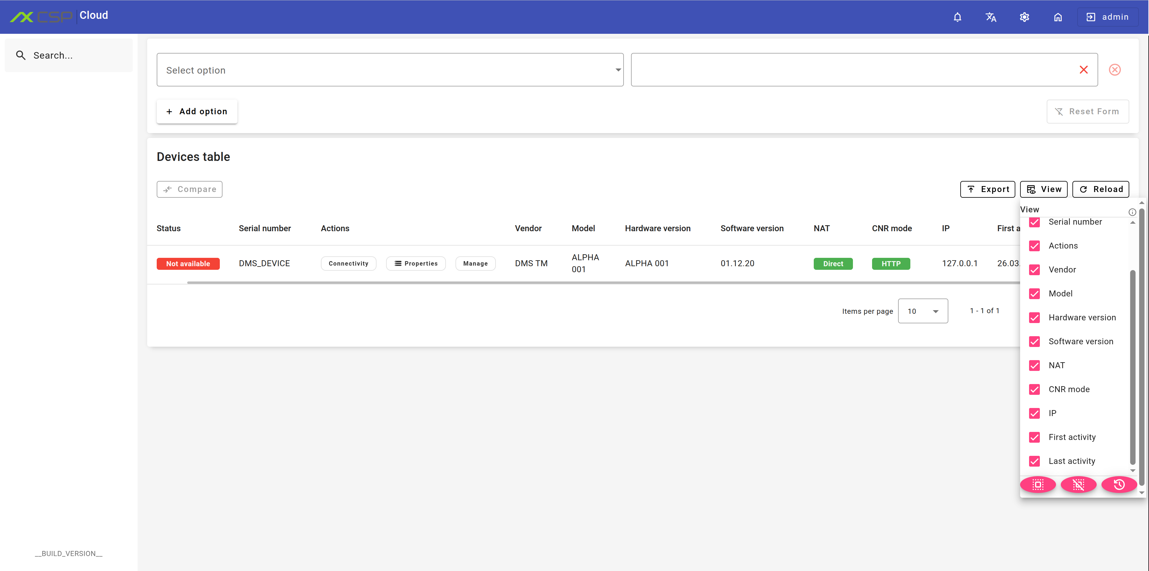
The device card is an automatically generated set of widgets that allow you to effectively manage the device. It's important to note that the set of these widgets may vary depending on the specific device, as it is formed based on the available TR-069 parameters of each CPE.
This section will describe in detail the main groups of widgets available in the device card.
CPE Overview
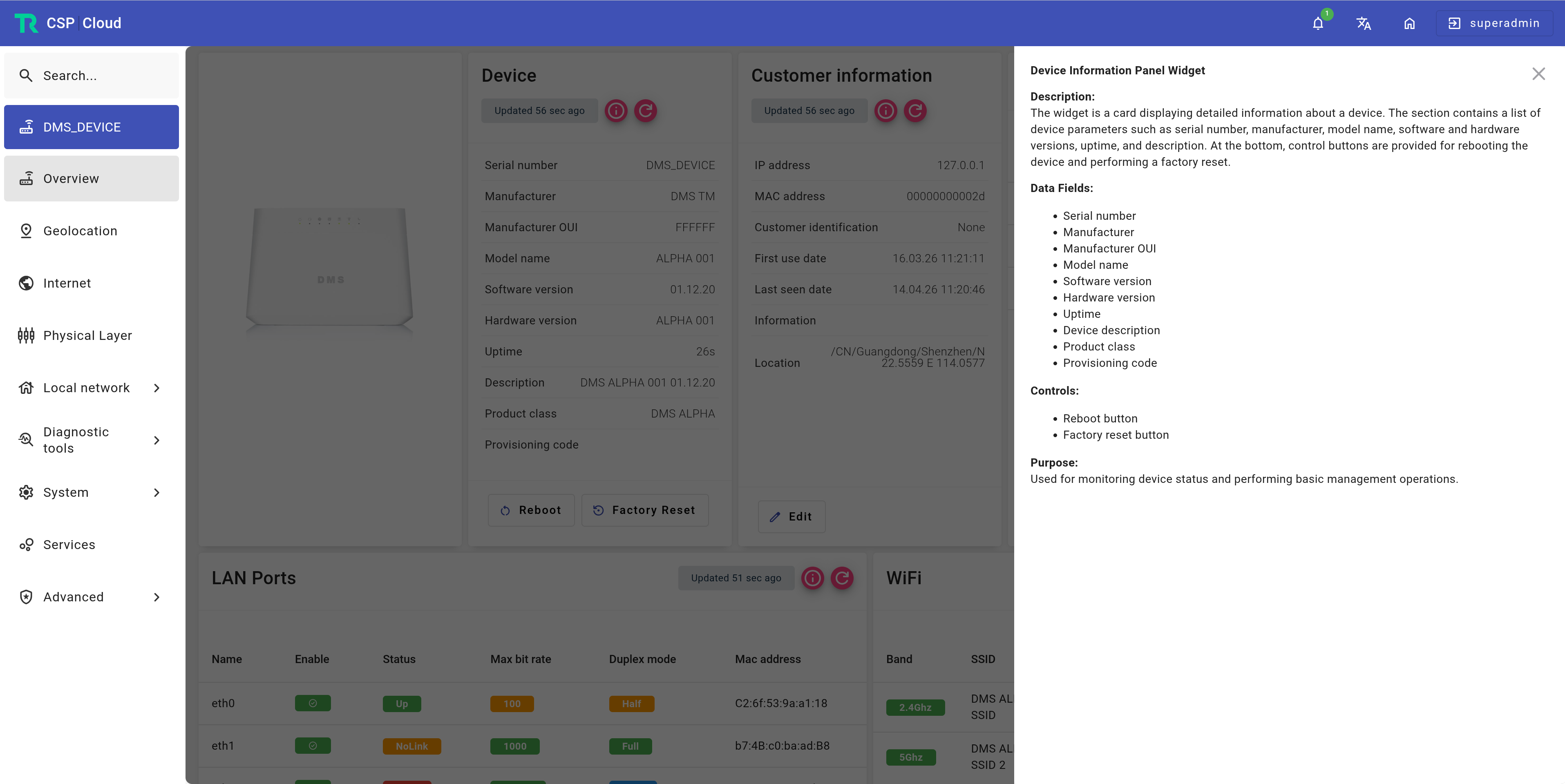
After selecting the necessary CPE and clicking the "Manage" icon, you will see a comprehensive set of widgets with information about this device. The top part will display the device image, and on the right - detailed information about the device, client, and connection status. The bottom part of the interface presents information about LAN ports and WiFi status.
The device layout presented in the table has been formed automatically. Due to the adaptive nature of the interface and the specifics of the data model of a particular CPE, certain functions may display or operate with limitations. If necessary, you can contact the administrator for additional information.
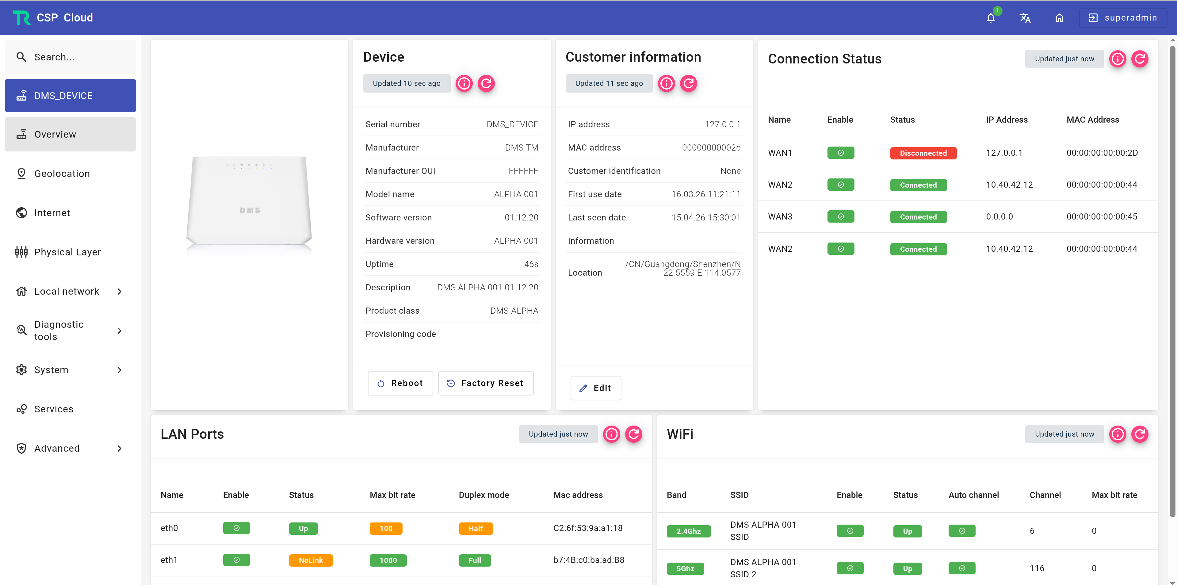
Detailed information with description of each widget can be obtained by clicking the "Exclamation mark" icon in the upper right corner of the corresponding widget. This will help better understand the purpose and capabilities of each interface element.
Internet
To provide general connectivity, you can use two types of protocols: IPoE and PPPoE.
IPoE Protocol
With IPoE, the user does not need to enter login and password when connecting to the Internet: the DHCP server automatically assigns an IP address and necessary configuration information. This saves IP addresses and speeds up data processing, as information flows do not contain encoded information. IPoE also allows subscribers to move within the network and automatically obtain an IP address when reconnecting. The technology supports connecting all devices in the home to the Internet: TVs, game consoles, smartphones, etc. In the IPoE information table, you can find data about connection type, connection status, IP and MAC addresses, DNS server address, and statistics of sent and received packets.
The most important information can be changed or updated. Click the "Pencil" icon to make necessary changes in the dialog box.
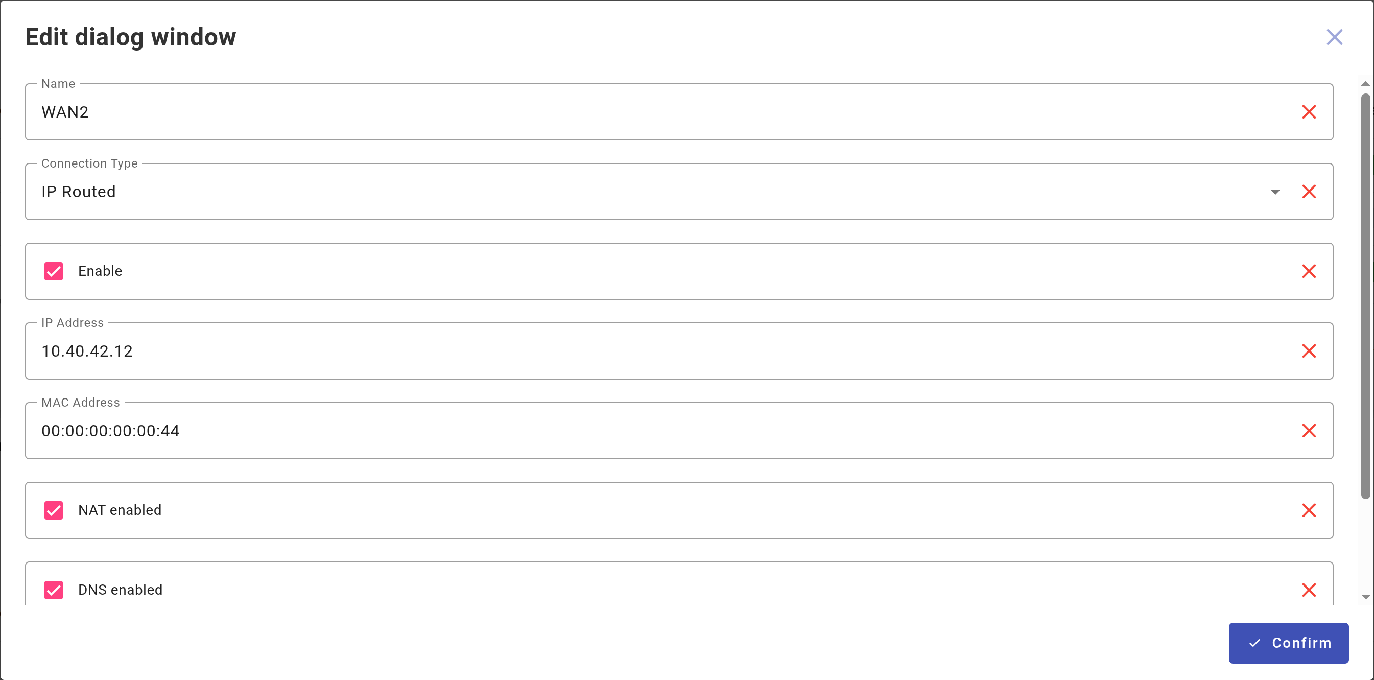
You can set "Name", "Connection Type", "IP address", "MAC Address", "DNS servers" according to your preference.
PPPoE Protocol
PPPoE (Point-to-Point Protocol over Ethernet) is a point-to-point data transmission protocol over Ethernet network. It creates a "tunnel" between the provider's server and the end CPE connected to the Internet. The connection is established using routers, modems, and other devices with Ethernet ports. PPPoE supports user authorization functions, as well as traffic compression and encryption. Information about the PPPoE connection is available for analysis in the table.
Location
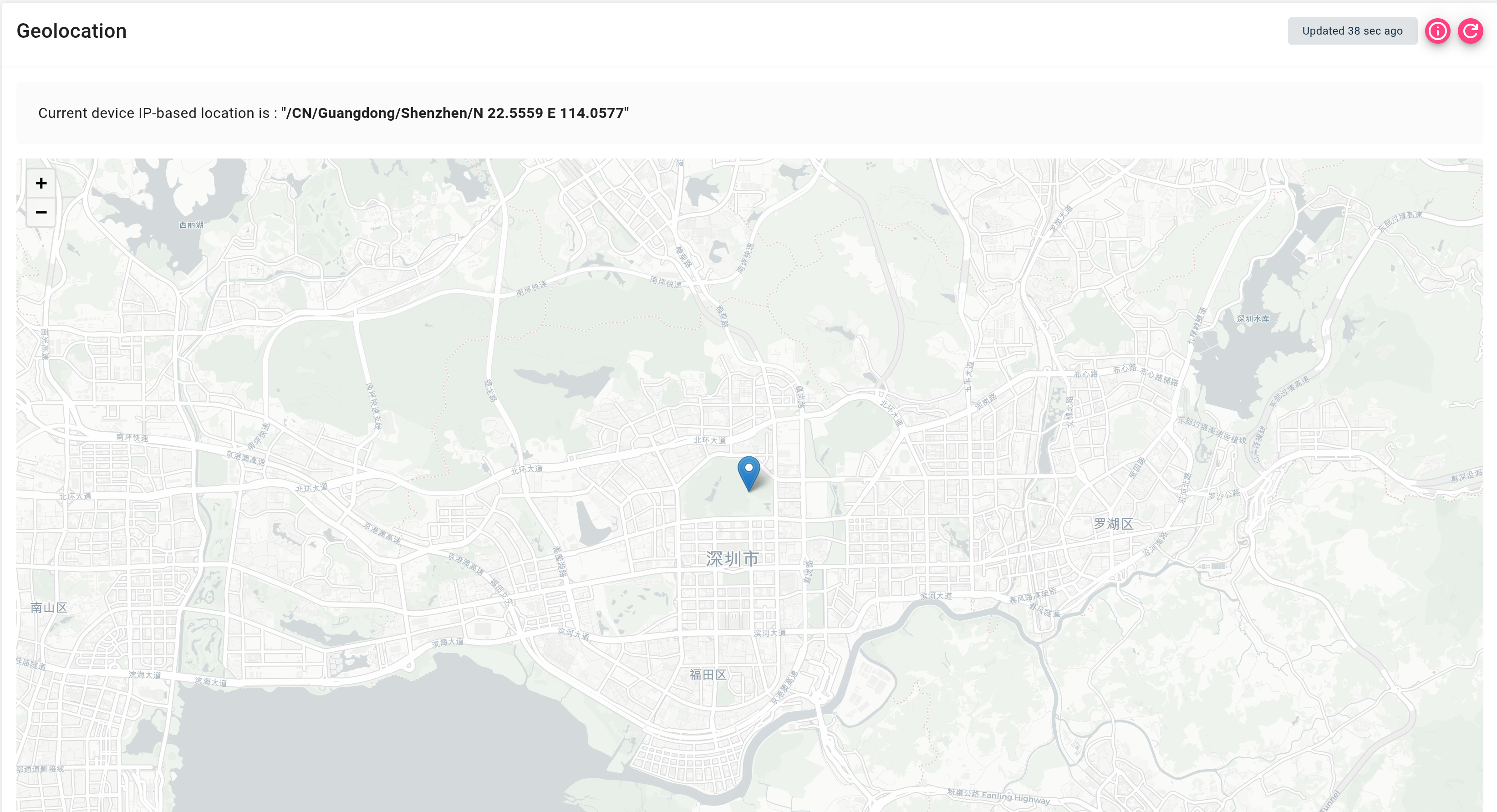
This section is used to display the location of the CPE if its "location" field is filled correctly. You can read more about this in the "Location Setup" chapter.
Physical Layer
This section is used to display information about physical connections with their statistics.
Local Network
This section is used to display information about the local network, including: WiFi, LAN, and Network Map.
WiFi
This section contains detailed information about WiFi parameters. The WiFi radar table in the Support Portal visualizes the selected CPE, as well as other nearby devices within range. The table clearly demonstrates the possible frequency range occupied by the selected device (2.4 GHz, 5 GHz or 6 GHz), as well as the quality of the channel on which it operates. The vertical axis of the graph displays the received signal strength (RSSI) in dBm, which is a critically important parameter for diagnosing problems related to device interruption and network dropout.
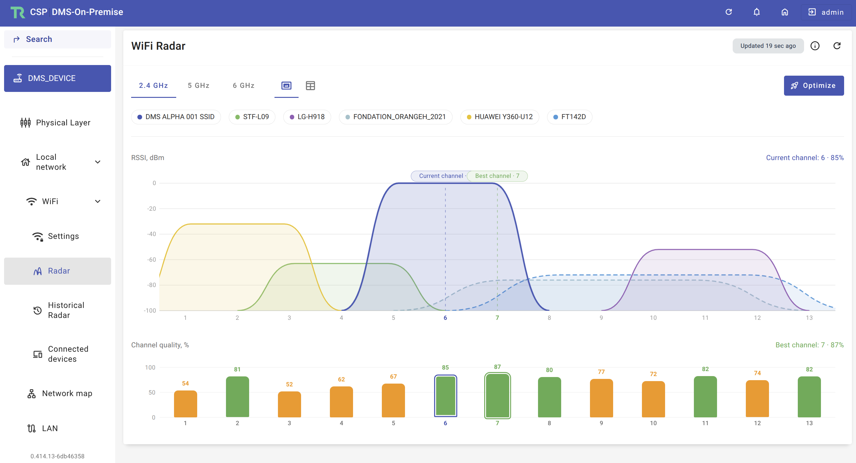
The table also displays the signal strength of neighboring devices that may affect the operation of your CPE. If necessary, you can hide one or more displayed neighboring devices from the graph for clearer visualization. Additionally, the channel quality graph for this device highlights the best and worst channels for optimal operation.
If you want to optimize the operation of the selected device in manual mode, press the "Optimize" button. In the appeared dialog window, select the desired channel, activate the channel change option, and confirm your decision by clicking the "Confirm" button to apply changes.
Network Map
The network map displays the hierarchical structure of network devices and interfaces, providing information about connection type, network addresses, and IP address lease times.
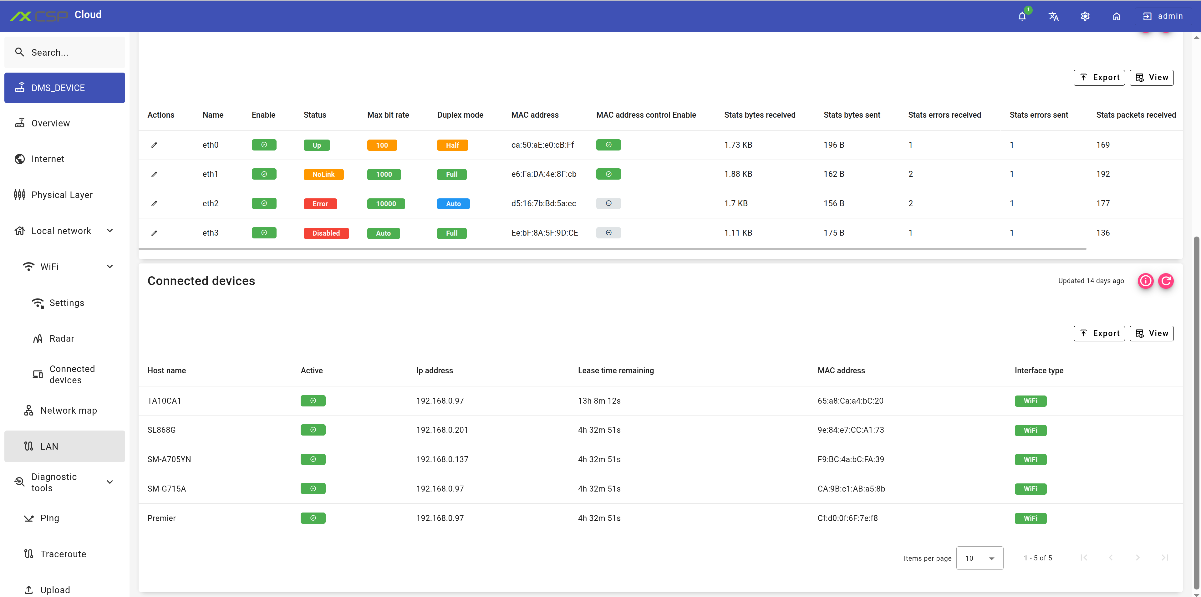
LAN
Displays existing LAN interfaces, their status, and state.
Diagnostic Tests
Diagnostic tests allow you to perform a series of procedures to determine the correct operation of the CPE, including: Ping, Traceroute, Upload, Download, NS Lookup.
System
The "System" section allows you to configure the management server, backup and recovery, firmware manager, users, time, hardware, remote access, as well as perform device log analysis.
Additional
The "Additional" section contains RPC (Remote Procedure Call), SQM, Port Forwarding, and Model Tree.
RPC
The "RPC" (Remote Procedure Call) section provides a powerful tool for interacting with devices through standardized TR-069 methods. Here you can select the required RPC scenario, run it, and get detailed execution results. Available RPC methods include such important operations as "GetRPCMethods", "GetParameterValues", "SetParameterValues", "GetParameterNames", "GetParameterAttributes", "SetParameterAttributes", "CWMP.AddObject", "CWMP.DeleteObject", "CWMP.Reboot", "CWMP.Download", and many others (full list available in the dropdown menu).
For example, consider the process of applying parameters using the "GetParameterValues" method. This method returns an array of string objects containing all values of the specified request parameters. To perform the operation, select the required RPC method (e.g., "GetParameterValues") and click the "Run RPC" button. More detailed information about RPC can be found in section A3.2 of the TR-069 specification.
After launching the operation, the system will display a special notification about task execution.
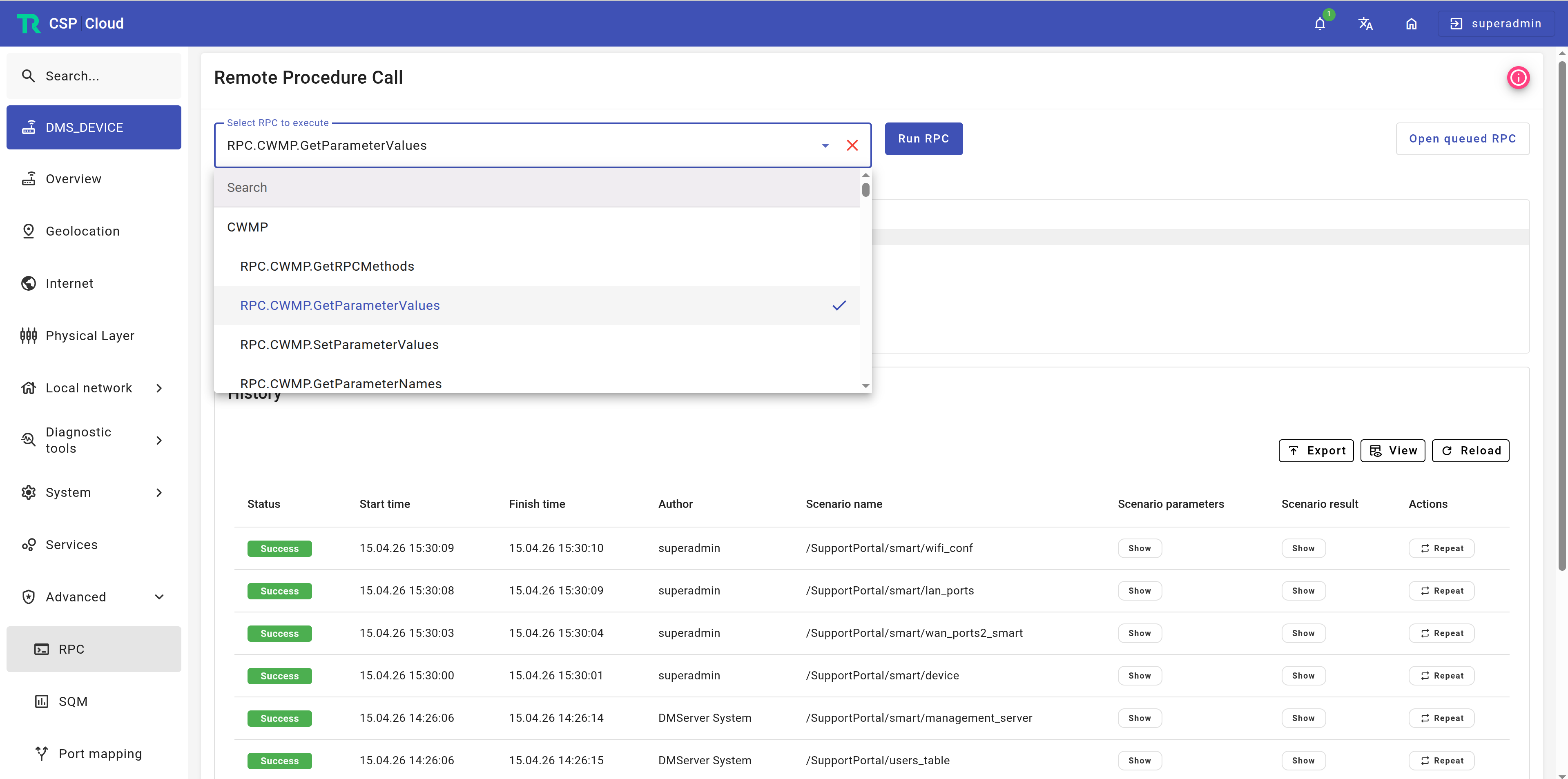
The results of the executed RPC task will appear in a special window in the center of the page. Below you will see a table with detailed RPC execution statistics, including start and end time of the operation, execution status, author, scenario parameters, and obtained results. To restart a previously executed RPC method, simply click the action button  opposite the corresponding scenario.
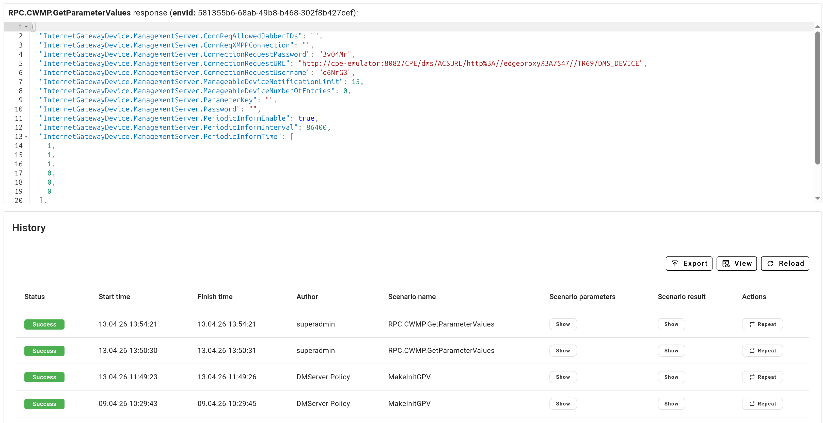
If you need to make changes to RPC parameters, you can use the RPC parameters editor.

In the opened window, enter the necessary custom parameters that will be applied during the next execution of the RPC scenario.
Port Forwarding
This section is designed for managing port forwarding rules on a network device. The functionality allows redirecting incoming connections from specific router ports to internal devices on the local network, which is especially useful for organizing access to services within the network.
Model Tree
A hierarchical navigation tree displaying the structure of configuration sections and device parameters. Allows the user to navigate through various configuration categories and manage them.